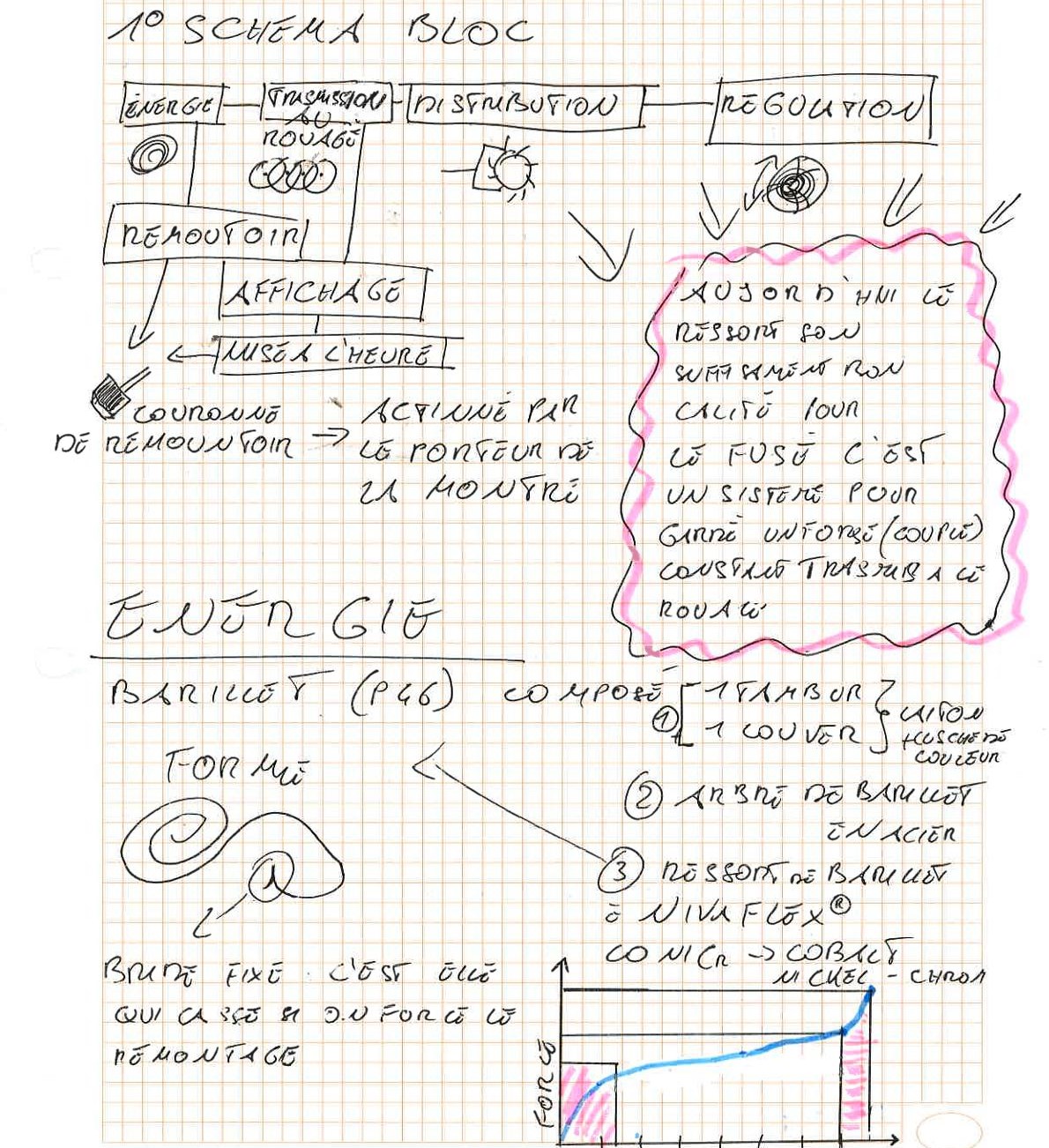
1. Block Diagram of the Mechanical Movement
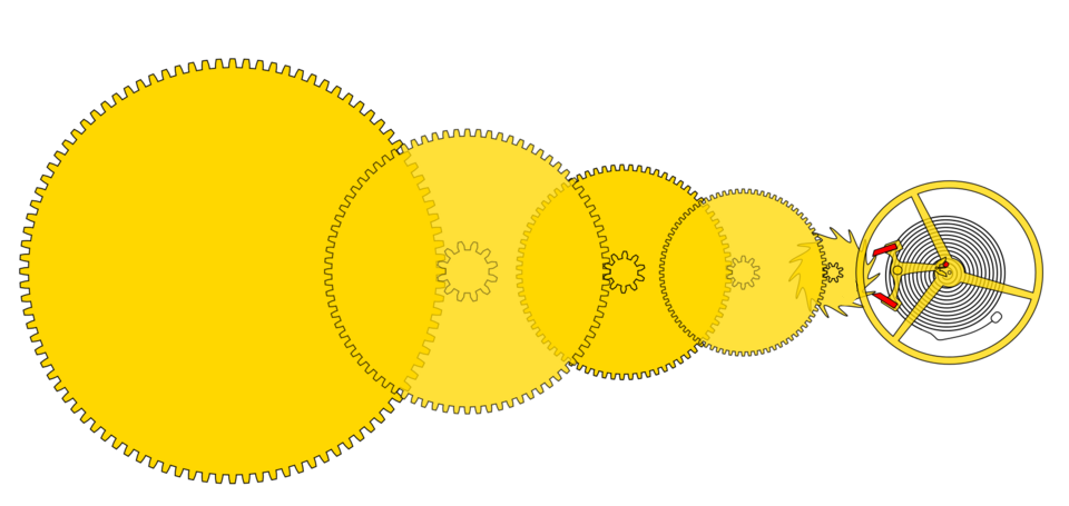
The block diagram defines the fundamental functional architecture of the manual winding mechanical watch. The accumulated energy is continuously transmitted, distributed, and regulated:
Step 1: Energy
The Mainspring & The Barrel
The engine of the watch. The mainspring, housed inside the barrel drum (1), stores mechanical energy during winding.
Step 2: Transmission
The Going Train
The reduction of force. The gear train (2) transmits the energy.
Step 3: Distribution
The Escapement
The kinematic converter. The escape wheel (3) transforms continuous rotary motion into impulses.
Step 4: Regulation
The Oscillator
The isochronous heart. The balance-spring assembly (4) dictates the absolute rhythm.
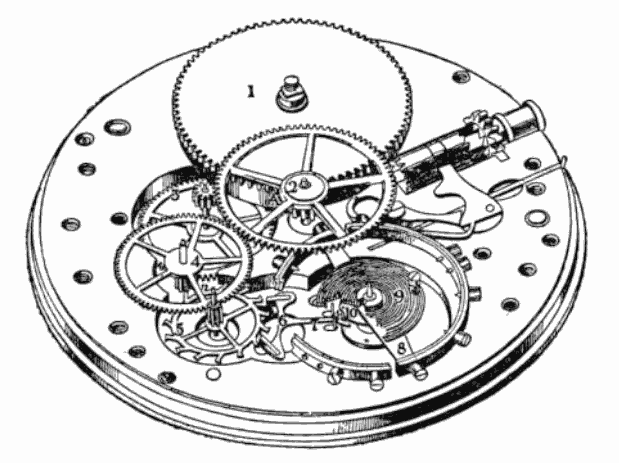
1
2
3
4
5
8
9
⚙️
1 Barrel
2 Center wheel
3 Third wheel
4 Seconds wheel
5 Escape wheel
8 Balance wheel
9 Hairspring
⚙️ Winding mechanism
📷 ORIGINAL HANDWRITTEN NOTE (01-02) — Block Diagram & Introduction
2. Motive Organ (Energy): The Barrel & Winding Systems
The barrel is the central component for storing potential energy in the mechanical movement.
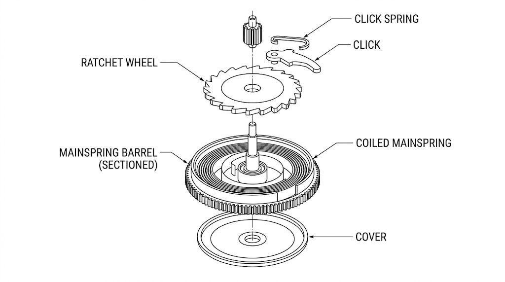
📷 TECHNICAL VIEW — Anatomy of the barrel and mainspring.
⚙️ Workshop Rule: On an automatic movement, manual winding via the crown simulates exactly the state of maximum charge reached by the rotor.
3. Mainspring Attachment & Torque Regulation
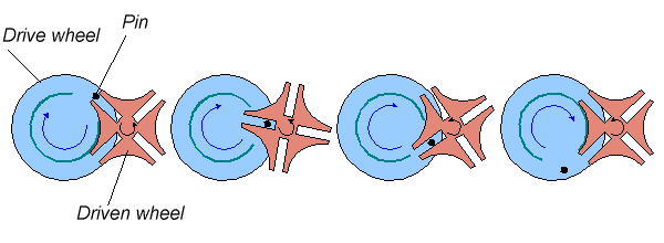
📷 TECHNICAL DIAGRAM — The Maltese Cross: blocking rotation to utilize the linear torque range.
📷 ORIGINAL HANDWRITTEN NOTE (01-03) — Mainspring Attachment, Maltese Cross & Fusée
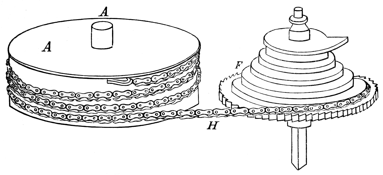
Constant Force: The Fusée and Chain
This historical mechanism acts as a continuously variable transmission to compensate for the loss of torque from the mainspring as it unwinds.
- Maximum winding: The spring is strong, the chain pulls on the small diameter of the fusée (short lever arm).
- Unwinding: The spring weakens, the chain pulls on the large diameter of the fusée (long lever arm), thus perfectly equalizing the force transmitted to the escapement.